Paper: Modelling and optimization of rotary vane seals.
Authors: Nikas, G. K., Burridge, G., Sayles, R. S.
Published
in: Proceedings of the
Institution of Mechanical Engineers (IMechE), Part J: Journal of
Engineering Tribology, 2007, 221(6), 699-715
Abstract
The present study deals with the formulation of the mechanics, elastohydrodynamics and performance of composite vane seals of rectangular cross-section and goalpost shape, such as those used in rotary vane actuators in aviation, automotive and industrial applications. After constructing the mathematical and computational model of such seals, results are obtained for an application involving a rotary vane actuator for aircraft wing control surfaces. Examples are presented both for steady-state and transient conditions (steady and unsteady motion). These are followed by an extensive parametric study to establish the effects of various parameters on sealing performance, such as the effects of the seal interferences, sealed pressure, speed, design clearances, operating temperature, and the degree of lubricant starvation. Sealing performance is assessed on the grounds of the mass leakage rate, hydrodynamic friction force and extrusion size during operation. The parametric study resulted in the construction of 144 diagrams with 432 performance curves in total. Based on this, the design and operational sealing parameters were optimized to maximize sealing performance, that is, to minimize leakage, friction and extrusion. There was excellent agreement between the theoretically derived optimum values and those recommended semi-empirically by the seal and actuator manufacturers as initial estimates. The parametric study showed that vane seals are objects of complex mechanical behaviour, requiring attention to detail in their design and application, not only to maximize performance, but, primarily, to establish sufficient sealing and avoid premature failure that could prove very costly indeed.
Some figures from this work
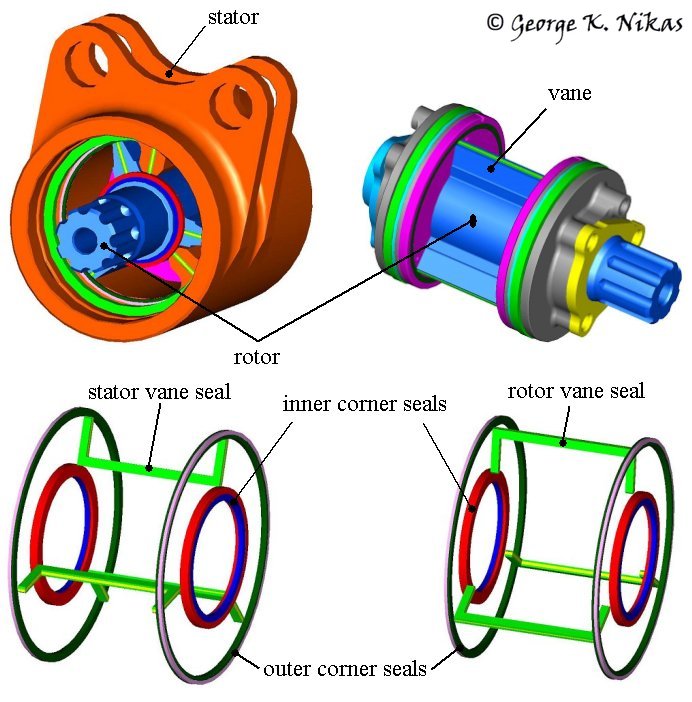
Figure 1 shows part of a rotary vane actuator with the stator, rotor and polymeric seals.
Fig. 1. Rotary vane actuator: stator, rotor and seals (courtesy Smiths Aerospace).
The stator and rotor vane seals pictured in Fig. 1 are the objects of study in the paper. The stator seals are mounted on the stator and the rotor seals are mounted on the rotor. The aforementioned seals (in green colour) are of goalpost shape, rectangular cross-section and comprise three parts: a centrally placed elastomeric part sandwiched between two composite Polytetrafluoroethylene (PTFE) parts, as depicted in Fig. 2.
Fig. 2. Composite vane seal.
The paper deals with the mechanics, elastohydrodynamics and performance evaluation of the vane seals in terms of leakage, hydrodynamic friction and extrusion during operation. Results have been derived as explained in the abstract earlier on this page, comprising 144 diagrams with 432 performance curves at three temperatures, namely at 54, +22 and +99 °C, and sealed pressures up to 35 MPa (350 bar). Half of those results are for fully flooded conditions of seal lubrication and half for starved conditions. The seals have been analysed in steady-state as well as in transient conditions (variable rotor angular speed) and further details of this study are available in the related research project of the authors.