Busak+Shamban (UK) ![]() (now Trelleborg
Sealing Solutions
(now Trelleborg
Sealing Solutions ![]() )
)
Project: Research of fundamental sealing mechanisms needed for zero-leakage high-reliability rotary vane actuators.
Clients:
Busak+Shamban (UK) ![]() (now Trelleborg
Sealing Solutions
(now Trelleborg
Sealing Solutions ![]() )
)
Sponsor: Department of Trade and Industry (UK) ![]()
Researcher: Dr George K. Nikas (Imperial College London, Mechanical Engineering Department).
Supervisors:
Dr Richard Sayles (Imperial College London, Mechanical Engineering Department).
Mr Guy Burridge (Busak+Shamban / Trelleborg).
Mr Chris Whitley (Smiths Aerospace Mechanical Systems).
Dr Gillian Richards (Department of Trade and Industry).
Mr Chris Carey (Department of Trade and Industry).
Project duration: 18 months (2003-2004).
Project cost: £112,000.
Technical report: A technical report was written by Dr Nikas for the clients and sponsor. The 121-page report contains 98 figures (including 189 diagrams) and 94 detailed equations.
Computer
software developed: program ROVAS. Elastohydrodynamics, mechanics
and performance analysis of composite seals of rectangular
cross-section, used in rotary vane actuators. Written in Fortran. Code
size: 1421 lines. Latest version: 1.1.3. Registered users: Smiths
Aerospace (UK) and Trelleborg Sealing Solutions (UK).
Summary
This was part of a larger project named SATOW (Surface Actuation for Thin and Optimised Wings); a news article about this project was published in Sealing Technology. The purpose of the author's project titled at the top of this page was the mathematical modelling of composite seals of rectangular cross section, resembling a goalpost. These are made for a new rotary vane actuator to replace conventional linear hydraulic actuators used in aircraft wings for the control of wing flaps. The actuators normally operate under high hydraulic pressure, usually up to 35 MPa (5000 lb/in2 or 350 bar), and with operating temperatures varying from -54 °C (during flight) to +100 °C or more (on the ground with aircraft engines running). The seals consist of three parts bonded together: two PTFE (Polytetrafluoroethylene) parts and one elastomeric part (Fig. 1).

Fig. 1. Goalpost composite vane seal.
The sealed-pressure differential is along the x-axis in Fig. 1 and sealing takes place on the horizontal seal section - side EFGH, and on each vertical section, for example, side ABCDEF. There are two types of goalpost seal in the system, a stator vane seal and a rotor vane seal, the difference between the two being that the stator seal is fixed on a stator and does not move, whereas the rotor seal is fixed on a rotor, which rotates to control the wing flaps of the aircraft.
The goal of the author's project was the development of a numerical model and related computer software to study the elastohydrodynamics and mechanics of the operation of the vane seals and to evaluate the effects of design parameters, for example, the mechanical properties of the seals and the effects of transient phenomena such as variable stroking velocity and oscillatory motion. Naturally, the study included the calculation of seal leakage and friction as well as the risk of extrusion of the vane seals under normal operating conditions, and concluded with the selection of the optimum values of design and operational parameters to minimise leakage, friction and extrusion, or achieve the best compromise, depending on the priorities and constraints of the system, as set by the manufacturers.
The modelling work involved the development of a numerical method to solve the one-dimensional, steady-state as well as transient forms of the Reynolds (elastohydrodynamic lubrication) equation in both Cartesian and polar coordinates for the horizontal and vertical seal sections for smooth contacts (that is, ignoring roughness effects as a first approximation). The analysis is based on analytical equations for the description of seal mechanics using the classic linear elasticity theory, which is suitable for this application based on published studies of the author. The developed method is stable and very fast, requiring only 5 hundredths of a second of CPU time of a 1.5 GHz PC for a steady-state analysis and about 15 seconds for a transient analysis, including all lubrication, mechanics and performance analysis computations for two seals (stator and rotor seal).
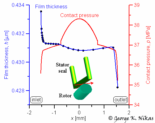
An example of the steady-state analysis for a stator vane seal is shown in Fig. 2. The rotor rotates clockwise at a constant angular velocity of 0.7 rad/s as the red arrow indicates and the graph shows the contact pressure and elastohydrodynamic film thickness across the horizontal section (or along the x-axis according to Fig. 1), from the inlet of the sealing contact to the outlet.

Fig. 2. Example of contact pressure and elastohydrodynamic film thickness for a stator seal horizontal section at -54 °C.
Publications of the author related to this work
Nikas, G. K., Burridge, G., Sayles, R. S. Modelling and optimization of rotary vane seals. Proceedings of the Institution of Mechanical Engineers, Part J: Journal of Engineering Tribology, 2007, 221(6), 699-715.
Nikas, G. K., Sayles, R. S. Modelling and optimization of composite rectangular reciprocating seals. Proceedings of the Institution of Mechanical Engineers, Part J: Journal of Engineering Tribology, 2006, 220(4), 395-412.
Nikas, G. K., Sayles, R. S. Study of leakage and friction of flexible seals for steady motion via a numerical approximation method. Tribology International, 2006, 39(9), 921-936.