Paper: Transient elastohydrodynamic lubrication of rectangular elastomeric seals for linear hydraulic actuators.
Author: George K. Nikas
Published in: Proceedings
of the Institution of Mechanical Engineers, Part J: Journal of
Engineering Tribology, 2003, 217(6), 461-473
Erratum: There an obvious misprint in the definition of strain εx in page 465 of the article for both the Hookean and the Mooney-Rivlin model, which was introduced at the journal during typesetting. The correct definition is εx= 1 Drod/d for the Hookean model and εx= 1 Drod/dseal for the Mooney-Rivlin model.
Abstract
A numerical model developed previously by the author to study rectangular rubber seals for reciprocating piston rods in hydraulic actuators is extended to include transient effects, considering the sealed pressure and the stroking velocity of the piston rod as time variables. The model incorporates various improvements regarding the treatment of seal extrusion, nonlinear seal elasticity effects, as well as the modelling of back-up rings at the air-side of the actuator, all of which have been dealt with individually in previous studies of the author. These new features are combined in the present model for a complete analysis of the leakage and friction performance of the seal-ring system under real transient operating conditions of industrial and aircraft actuators, including thermal effects and rough-contact analysis, and covering the widest applicable range of sealed pressures (over 0.1 MPa) and operating temperatures (60 to +140 °C).
Some figures from this work
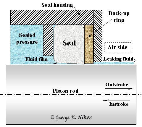
The hydraulic actuator and seal configuration for the model is shown in Fig. 1. The actuator contains fluid under pressure, usually between 0.1 and 35 MPa. The piston rod reciprocates and fluid leaks under the seal, past the (optional) back-up ring, and escapes to the air side of the system. The back-up ring supports the seal and prevents extrusion damage but, being normally in contact with the piston rod, acts as a seal, too. Both the sealed pressure and the stroking velocity are, generally, time variables.
Fig. 1. Configuration for the seal model.
Figure 2 below shows the computed seal-ring system mass leakage rate and the friction force on the seal for the sealed pressure and stroking velocity scenario shown on the first (top) diagram, which comes from a real industrial application.


Fig. 2. Example of full transient case, including back-up ring.
The mathematical model incorporates transient elastohydrodynamics of rough, soft contacts in two dimensions, linear and non-linear mechanics of an elastomeric seal and a metallic, soft anti-extrusion ring, analysis of possible extrusion effects for the seal, as well as complete freedom in deciding which design parameters to vary in the simulation. No major simplifying assumptions have been made and the leakage results have been experimentally verified in dedicated rigs at Smiths Aerospace after a rigorous test program involving hundreds of tests that lasted several months. However, the computed friction is much lower than that found experimentally and similar results have been reported in the literature before, attributed to the boundary mode of lubrication of the present case study and because the model has currently omitted possible adhesion effects. Clearly, friction modelling needs to be improved with the addition of secondary effects that are usually associated with boundary lubrication before the model can be considered satisfactory in terms of friction.
For more information in this research area, please see the author's related sealing project.