Paper: Mathematical analysis of the entrapment of solid spherical particles in non-conformal contacts.
Author: George K. Nikas
Published
in: Transactions of the American Society of Mechanical
Engineers (ASME), Journal of Tribology, 2001, 123(1), 83-93
Abstract
The process of entrapment of small spherical particles in both lubricated and dry, line and point contacts, is mathematically analysed and a criterion is postulated in order to evaluate the possibility of entrapment. The analysis is generalized for non-conformal contacts, operating under mixed rolling-sliding conditions with emphasis given to elastohydrodynamic contacts. This study aims to provide the methods, suitable for easy computer programming, to evaluate the risks of surface damage from small debris particles in machine element applications and to make the selection of proper filtration more confined.
Some figures from this work
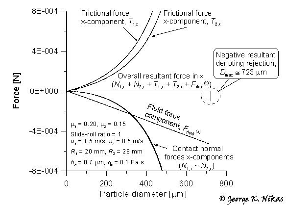
A couple of examples from this paper are shown below. Figure 1 shows the x-components of the various forces (mechanical and fluid forces) acting on a spherical particle at the entrance of a typical elastohydrodynamic line contact (central film thickness = 0.7 microns) as the particle barely touches the counterfaces of the contact. The figure shows how these forces vary with the particle diameter and reveals the maximum particle diameter for entrapment: if a particle has a diameter greater than that critical value, it will be rejected from that particular contact. The critical diameter is calculated by checking the sign of the x-resultant force on the particle: at the point where this resultant force becomes negative (see Fig. 1), the particle has reached its maximum possible size for entrapment.

Fig. 1. x-components of forces on a particle (line contact).
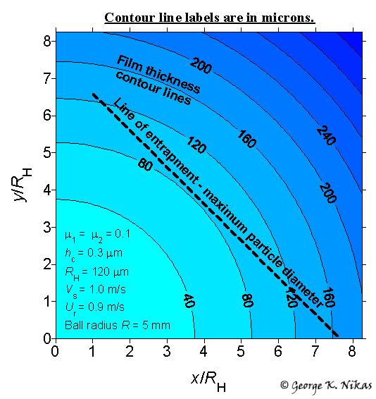
Figure 2 below is the adaptation of Fig. 1 for point contacts and shows a contour map of the film thickness in a typical point contact. On the same map, the “line of entrapment” is drawn. This line gives the maximum particle diameter for entrapment. It is found that this line is almost straight, inclined at about 45° to axes x and y and that this behaviour is typical for similar cases. In this example, it gives a maximum particle diameter for entrapment purposes between 80 and 170 microns, depending on the position where a particle comes in contact with the counterfaces.

Fig. 2. Contour map of film thickness in a point
contact and