Project:
Determination of polymeric sealing principles for end user high
reliability.
Clients:
Sponsor: Department of Trade and Industry (UK) ![]()
Researcher: Dr George K. Nikas (Imperial College London, Mechanical Engineering Department).
Supervisors:
Dr Richard Sayles (Imperial College London, Mechanical Engineering Department).
Mr Guy Burridge and Mr Morgan Gilbert (Polymer Sealing Solutions Ltd).
Mr David Goddard and Mr Robert Almond (Smiths Aerospace Actuation Systems - Cheltenham).
Mr Richard Tamplin and Mr D. Mountney (Smiths Aerospace Actuation Systems - Wolverhampton).
Mr D. Bracknell (QinetiQ, Department of Trade and Industry).
Project duration: 18 months (1999-2001).
Project cost: £172,000.
Technical report: A technical report was written by Dr Nikas and distributed to the supervisors of the project. The 124-page report contains 60 figures and 94 detailed equations.
PowerPoint presentation: A final PowerPoint presentation was delivered by Dr Nikas at the end of the project to all partners to summarize the theoretical work done and important findings.
Related computer software: program SEAL. Elastohydrodynamics, mechanics and performance analysis of rectangular elastomeric seals and back-up rings for linear hydraulic actuators. Written in Fortran. Code length: 2549 lines. Latest version: 1.1.1. Registered users: Smiths Aerospace (UK) and Busak+Shamban (UK).
Summary
The purpose of this project was to derive a fundamental understanding of all parameters and their inter-relationship, to satisfy the zero-leakage requirements of hydraulic linear motion assemblies. These demands manifest themselves with the requirement of higher reliability and implicitly with lower life cycle costs. Together with the necessary increased performance stipulations it is essential to define the parameters, underlying principles and properties of all aspects contributing to the performance of dynamic sealing.
Relatively little fundamental research has been performed/published in recent years on the basic sealing mechanisms of low modulus, polymeric, reciprocating seals. In view of the importance and increasingly widespread use of such basic engineering components, it is essential that some of the more recent tribological and materials analysis techniques be applied to modern seal designs in order to gain a better and updated understanding of seal performance. Exploitation of this understanding as the basis of general design criteria to achieve zero leakage hydraulic equipment is the ultimate goal.
Specifically, the theoretical part of this project involved the mathematical modelling of rectangular elastomeric seals used in aircraft actuators and hydraulic systems with linearly reciprocating piston rods. The assembly for the model is shown in the next figure.
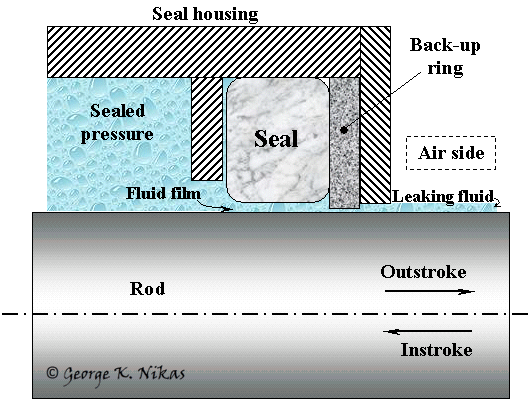
Configuration for the seal model.
The modelling comprises the stress analysis and solution of the rough, transient, isothermal elastohydrodynamic lubrication problem of such seals under high pressures (for example, 34 MPa (5000 lb/in2 or 345 bar) and operating temperatures in the region -55 to +135 °C. Because of the finite strains imposed, a Mooney-Rivlin type nonlinear elasticity model was used to calculate the contact stresses and strains in the body of the seal, together with the classical Hookean model of linear isotropic elasticity, the latter used for comparison and verification purposes. Thermal strains due to temperature differentials are also incorporated in the analysis for both models. A back-up ring is modelled at the air-side of the actuator and its effect on the leakage performance of the system is evaluated. A computer program was compiled, incorporating all aspects of the model, and offers fast solutions for any operating conditions. Leakage rates, frictional forces and friction coefficient are all calculated fast and related to the operating parameters of a particular application.
The target is to predict the dynamic behaviour of the seal and to minimize leakage throughout the range of operating conditions. The theoretical study is backed up by experimental research through the assembly of a test rig to simulate the working environment of such seals and study leakage under controllable conditions.
An example from the simulation is shown in the next figure. It refers to the film thickness map at a rod-seal rough contact during an outstroke. Darker blue areas indicate thicker film whereas lighter blue areas indicate thinner film and red areas indicate roughness asperities in contact (zero film thickness). Notice the film collapse as the sealed pressure is decreased.
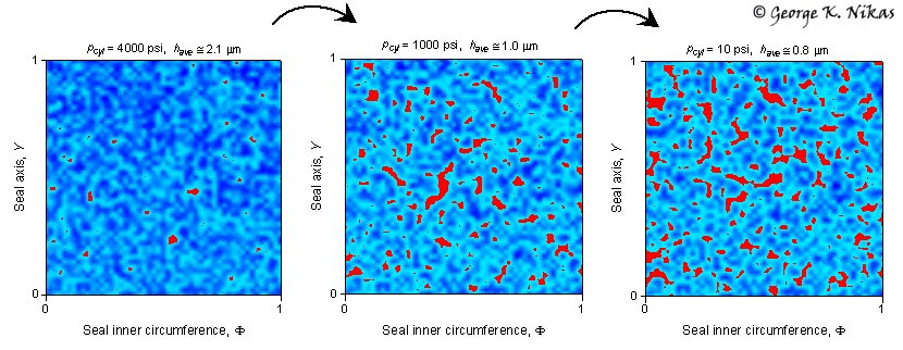
Film-thickness map at a rod-seal rough contact (red areas indicate solid contact).
From left to right, sealed pressure = 4000 lb/in2, 1000 lb/in2 and 10 lb/in2.
Average film thickness = 2.1, 1.0 and 0.8 microns From left to right, respectively.
Publications of the author related to this work (most recent appear first)
Nikas, G. K. Eighty years of research on hydraulic reciprocating seals: review of tribological studies and related topics since the 1930s. Proceedings of the Institution of Mechanical Engineers, Part J: Journal of Engineering Tribology, 2010, 224(1), 1-23.
Nikas, G. K. Research on the tribology of hydraulic reciprocating seals. First chapter (pp. 11-56) in the book entitled "Tribology Research Trends" (Ed.: T. Hasegawa). Nova Science Publishers, New York, USA, 2008. ISBN: 978-1-60456-912-4.
Nikas, G. K. Fundamentals of sealing and tribology of hydraulic reciprocating seals. Proceedings of the 1-day seminar "Focus on Reciprocating Seals"; organised by the Tribology Group of the Institution of Mechanical Engineers (IMechE), London, England, 25 June 2008.
Nikas, G. K., Sayles, R. S. Computational model of tandem rectangular elastomeric seals for reciprocating motion. Tribology International, 2006, 39(7), 622-634.
Nikas, G. K., Sayles, R. S. Nonlinear
elasticity of rectangular elastomeric seals
Nikas, G. K. Theoretical study of solid back-up rings for elastomeric seals in hydraulic actuators. Tribology International, 2004, 37(9), 689-699.
Nikas, G. K. Sayles, R. S. Nonlinear
elasticity of rectangular elastomeric seals
Nikas, G. K. Transient elastohydrodynamic lubrication of rectangular elastomeric seals for linear hydraulic actuators. Proceedings of the Institution of Mechanical Engineers, Part J: Journal of Engineering Tribology, 2003, 217(6), 461-473.
Nikas, G. K. Analytical study of the extrusion of rectangular elastomeric seals for linear hydraulic actuators. Proceedings of the Institution of Mechanical Engineers, Part J: Journal of Engineering Tribology, 2003, 217(5), 365-373.
Nikas, G. K. Elastohydrodynamics and mechanics of rectangular elastomeric seals for reciprocating piston rods. ASME Journal of Tribology, 2003, 125(1), 60-69.
Rana, A., Sayles, R., Nikas, G., Jalisi, I. An experimental technique for investigating the sealing principles of reciprocating elastomeric seals for use in linear hydraulic actuator assemblies. Proceedings (on CD-ROM) of the 2nd World Tribology Congress, 3-7 September 2001, Vienna, Austria.
